PWM
One of the most useful pieces of hardware in the Raspberry Pi is the Pulse With Modulator (PWM). With a Clock as an input, and a GPIO as an output, the PWM generates repeating square waves of defined durations and pulse widths:
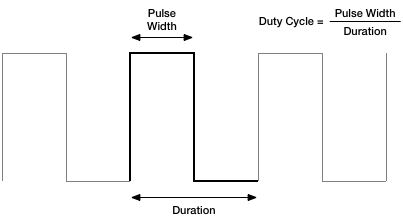
These have a wide variety of uses. One of the most fundamental is dimming LEDs and controlling other voltage-sensitive components, such as varying the speed of a motor. By using a PWM, and varying the duty cycle, we can vary the brightness of LEDs linearly. Since at a 50% duty cycle, the LED is only receiving half of the energy, it will only be half as bright; or the motor half the speed.
Another is providing basic analog signals, for example servo motors use the duty cycle of a digital signal to determine the position for the arm to be in.
Finally the PWM can be used to convey arbitrary digital logic signals consisting of periods of +3.3V and periods of 0V.
The documentation for the PWM can be found in p138–147 of the datasheet, except for the critically important register offset which we have to obtain from the errata.
let peripheralBlockSize = 0x1000
let pwmRegistersOffset = 0x20c000

guard let pwmRegisters = mmap(nil, peripheralBlockSize, PROT_READ | PROT_WRITE, MAP_SHARED, memFd, off_t(peripheralAddressBase + pwmRegistersOffset)),
      pwmRegisters != MAP_FAILED else { fatalError("Couldn't mmap PWM registers") }

let pwmControlOffset = 0x00
let pwmRange1Offset = 0x10
let pwmData1Offset = 0x14

let pwmControl = pwmRegisters.advanced(by: pwmControlOffset).assumingMemoryBound(to: Int.self)
let pwmRange1 = pwmRegisters.advanced(by: pwmRange1Offset).assumingMemoryBound(to: Int.self)
let pwmData1 = pwmRegisters.advanced(by: pwmData1Offset).assumingMemoryBound(to: Int.self)
The Raspberry Pi provides two PWM channels, however they don't act entirely independently. For most of this document we'll use PWM Channel 1, but will briefly explore using Channel 2 as well later.
The PWM hardware doesn't function on its own, it requires a clock as an input to act as a timing source. A dedicated PWM clock exists and sets the frequency of both PWM channels.
Configuring the output frequency of a clock is a topic in its own right and as such given its own page, which includes the addresses of the registers for the PWM's clock source. For the PWM, what matters is how that translates to the pulse width and duration of the output.

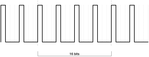
The PWM is fundamentally a digital piece of hardware, so operates on a sequence of bits. A bit of one means that the output will be a +3.3V high, while a bit of zero means that the output will be a 0V low. The above output is thus the following repeated bit pattern:
| 1 | 1 | 1 | 1 | 0 | 0 | 0 | 0 | 1 | 1 | 1 | 1 | 0 | 0 | 0 | 0 |
The frequency of the input clock defines the bit rate, the length in time of one bit, whether it be a zero or a one. The bit pattern defines the resulting pulse-width, duration, and thus duty cycle.
In the example above, given an input clock frequency of 1 Mhz, the pulse-width would be 4µs and the duration 8µs, with a 50% duty cycle.
In addition to a clock acting as a timing source input, the PWM needs a GPIO to act as an output. This requires configuring the GPIO to an alternate function corresponding to the desired PWM channel:
| GPIO | PWM Channel 1 | PWM Channel 2 |
|---|---|---|
| Alt 0 | GPIO12 | GPIO13 |
| Alt 5 | GPIO18 | GPIO19 |
Note that the documentation is rather inconsistent as to whether it refers to the first PWM channel as PWM Channel 1 or PWM0, and more confusingly, the second as PWM Channel 2 or PWM1. For clarity I'm only using the channel numbers here.
With the input clock frequency configured, and the output GPIO set to the correct alternate function, we can configure the PWM itself.
The "default" mode of the PWM is the one that we get by enabling the PWM Channel with all of the other option bits set to zero. This mode is the most suitable for dimming LEDs, or adjusting motor speeds, because it outputs pulse-widths of as little as a single bit in length at a high frequency.
As with all of the modes, the output signal is controlled by the PWM Channel 1 Range and PWM Channel 1 Data registers. The two configure the duty cycle desired, ie. the ratio of time that the output is high vs. low.
We place the duration into the Range register, and the pulse-width into the Data register, and then we enable the PWM by setting the Channel 1 Enable bit and leaving all others as zero:
pwmRange1.pointee = 100
pwmData1.pointee = 25

pwmControl.pointee = (1 << 0)
In this mode, the units of value for the Range and Data registers are largely irrelavant; they serve simply to set the duty cycle—in this case, 25%. The actual pulse-width and duration times will be as short as possible.
An alternative mode for the PWM is the mark-space (M/S) mode. In this mode, the Range and Data registers still configure the duty cycle of the output, but now they directly configure the duration and pulse-width respectively, in units of bits.
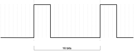
Now the output is high for as many bits as specified in the Data register, and then low for as many bits remaining for the Range register.
When we configure this, in addition to enabling the channel, we also set the Channel 1 Mark-space Mode bit.
pwmRange1.pointee = 16
pwmData1.pointee = 4

pwmControl.pointee = (1 << 0) | (1 << 7)
Since this mode gives us direct control over the length in time of the pulse-width and duration, it's very suitable for controlling devices such as servo motors which require specific timings.
The final alternative mode for the PWM is the serializer mode, and in this mode, the Range and Data registers are interpreted quite differently.
The Range register still, as with the Mark-space mode, specifies the duration of the output signal in bits, however now the Data register directly specifies the bit pattern which the PWM will output.
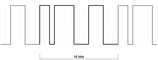
The bits of the Data register are interpreted from most-significant to least-significant, when a bit is one, the output will be a +3.3V high; and conversely when a bit is zero, the output will be a 0V low. As before, the length in time of a bit is driven by the input clock.
Since the Data register is 32-bits in size, the values of the Range register are important. When the Range register is exactly 32, all 32-bits of the Data register will be used. But when the Range register is less than 32, the duration is reduced as you would expect, and the Data register will be truncated with only the most-significant bits used.
If the Range register is greater than 32, the full Data register will be used, and since the duration is extended as you would expect, the remaining time is filled with the output as a 0V low (unless the Silence Bit bit is set, in which case a +3.3 high instead).
pwmRange1.pointee = 16
pwmData1.pointee = 0b1101111000111000 << 16

pwmControl.pointee = (1 << 0) | (1 << 1)
Note that we have to shift the 16-bits of data in our example to the left so that it occupies the 16 most-significant bits of the Data register.
This mode gives us the most flexibility over the output signal, and is ideal for custom logic signals; though obviously constrained to those of 32-bits or less in length.
Normally the PWM uses the contents of the Data register to determine the pulse-width or logical signal, but alternatively it can use a FIFO buffer.
This buffer is somewhat larger, with room for 16 words of 32-bits; and since it operates first-in-first-out, we can write new words into it as they are consumed.
Before we use the FIFO we should clear it to ensure that there's no lingering, unconsumed, data from the last user. We do this using the Clear Fifo bit of the Control register.
pwmControl.pointee |= (1 << 6)To set use the FIFO instead of the Data register, we set the Use FIFO bit in addition to whatever mode bits we desire, and the Enable bit. For example, enabling with the Serializer mode and FIFO would be:
pwmControl.pointee = (1 << 0) | (1 << 1) | (1 << 5)
To add a new word to the FIFO, we use the FIFO Input register. This can be combined with any mode, and each word is consumed at the multiple of the bit-rate configured in the Range register. When using the FIFO, the Data register is not used.
let pwmFifoOffset = 0x18

let pwmFifo = pwmRegisters.advanced(by: pwmFifoOffset).assumingMemoryBound(to: Int.self)

pwmRange1.pointee = 16
pwmFifo.pointee = 0b1101111000111000 << 16
pwmFifo.pointee = 0b1111000011110000 << 16
pwmFifo.pointee = 0b1100001100001111 << 16
We can perform this as often as we like, but we should also be cautious as writing to the FIFO when it's already full will have no effect. We can check the PWM Status register to determine the state:
let pwmStatusOffset = 0x04

let pwmStatus = pwmRegisters.advanced(by: pwmStatusOffset).assumingMemoryBound(to: Int.self)

if pwmStatus & (1 << 0) != 0 {
    // FIFO is Full.
    // We cannot write.
} else if pwmStatus & (1 << 1) != 0 {
    // FIFO is Empty.
    // We must write.
} else {
    // FIFO is neither Empty or Full.
    // We can write if we like.
}
Should the FIFO become empty, there are two possible outcomes determined by the Repeat Last Data bit of the Control register. When that bit is one, the last word in the FIFO will be repeated until a new word is written; when that bit is zero, the FIFO should instead act as if a zero word was written—in practice, the Raspberry Pi sometimes repeats the last word anyway, if it was regular-looking enough, so beware of relying on this functionality.
The Raspberry Pi has two PWM channels, but they are not entirely independent from each other. This makes them difficult to use separately.
Firstly they share a clock source, so when you configure the output frequency of the PWM clock, you are configuring it for both PWM channels. The only way to vary the rate is therefore on the mode, range, and data of each channel.
Secondly, if using the FIFO, they both share that as well. What's more, they share it in a lock-step fashion. The first write to the FIFO goes into the buffer for channel 1, and the second to channel 2, the third to channel 1, fourth to channel 2, and so on.
Not only does this mean that there is only half of the buffer space available to each channel as before, but now the ranges have to be congruent for each other as there is no way to just write to the FIFO for channel 2 if that one is draining faster than the buffer for channel 1.
This is especially important when using DMA with the PWM, not only because the writes have to be considered for both channels, but there is also only one DREQ signal from the PWM hardware, and one threshold level.
If all of these limitations can be overcome, channel 2 is controlled by bits 8–15 of the Control register, with the individual bits in the same position as those for channel 1, just shifted left by 8 bits. For the Range and Data registers, separate ones for channel 2 are at different offsets:
let pwmRange2Offset = 0x20
let pwmData2Offset = 0x24

let pwmRange2 = pwmRegisters.advanced(by: pwmRange2Offset).assumingMemoryBound(to: Int.self)
let pwmData2 = pwmRegisters.advanced(by: pwmData2Offset).assumingMemoryBound(to: Int.self)

pwmRange2.pointee = 16
pwmData2.pointee = 4

pwmControl.pointee = (1 << 8) | (1 << 15)
Note that bit 14 is unused, since it would correspond to bit 6, the Clear Fifo bit, which already applies to both channels simultaneously.
We've already covered the FIFO Empty and Full status bits in the status register above, which are set when the appropriate conditions are true. In addition, there are debugging status bits which are set when the appropriate PWM Channel is transmitting; the Status register has four of these, despite there being only two channels.
if pwmStatus & (1 << 9) != 0 {
    // Channel 1 is transmitting.
}
The rest are read/clear bits, where we can obtain the current state by reading from them which is either false if the condition has not occurred, and true if it has, and after reading the value remains until cleared. To clear we write one to the appropriate bit.
For example, the Gap Occurred register lets us know if the FIFO ran to Empty for a given channel. If this happens we can take action, but we should also clear the error so we can see if it happens again.
if pwmStatus & (1 << 4) != 0 {
    // Gap Occurred on Channel 1.

    pwmStatus |= (1 << 4)
}
The data sheet lists the full set of error conditions that can be reported.